Introducción
En este post vamos a ver cómoutilizar un M-Duini WiFi como un Access Point para un Servidor Web. Vamos a aprender un modo en el que no necesitamos estar conectados a un router para controlar al M-Duino. Por lo tanto, el M-Duino, específicamente la placa ESP32 que hay en su interior, no hará falta que esté conectada a una red cableada (como un router), esto se llama soft-AP (soft Access Point). En este ejemplo, vamos a usar un M-Duino 21+ con WiFi/BLE aunque puedes utilizar cualquier modelo de nuestra familia WiFi/BLE.
Requisitos
Aquí tienes el link para ver los dispositivos disponibles con estas características y uno para descargar las Boards de Industrial Shields:
- Família WiFi & Bluetooth PLC
- Instalando las Boards de Industrial Shields en Arduino IDE (Actualizado)
Explicación del ejemplo
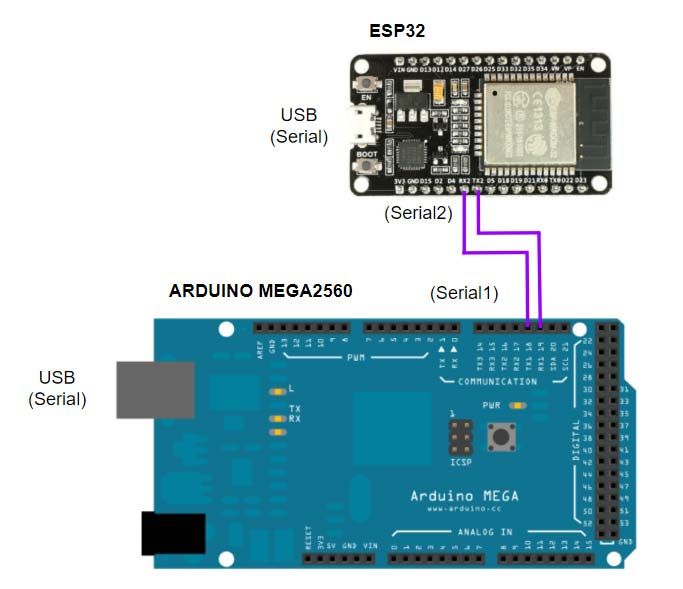
En primer lugar, tenemos que entender cómo la placa PLC MEGA2560 y el módulo WiFi ESP32 están conectados y cómo se comunican entre sí. Aquí tenemos un esquema para visualizar las conexiones internas entre el módulo ESP32 Devkit V1 y el Arduino Mega2560 interno:
Código del ESP32
En esta parte del programa, veremos cómo se implementa el Punto de Acceso. En primer lugar, hay que incluir la librería WiFi.h para trabajar con ciertas funciones de este módulo. Después de esto, el código inicializa todas las variables.
En el bloque del setup, este inicializa los puertos Serie, ejecuta la función para conectarse a la red Wi-Fi con un SSID y la contraseña, configurando la dirección IP también y haciendo el begin del server.
En el bloque del loop, después de todas las inicializaciones convenientes, hay una estructura condicional con whiles e ifs la cual controla todas las conexiones de los clientes y, después, hay una de la partes más importantes; esta activa y desactiva los GPIOs. En esta estructura, dependiendo del índice de la cabecera de la página del servidor, si una de las salidas (Q0_0 o Q0_1) es activada o desactivada, la variable var cambia su valor, el estado de la salida cambia convenientemente y el número del estado se escribe en el puerto del Serial2 (para enviarlo al Arduino MEGA). Ten en cuenta que los números de estado son los siguientes:
0 ---> Q0_0 off 8 ---> Q0_1 off
1 ---> Q0_1 on 9 ---> Q0_1 on
Después de estos comandos, los siguientes son utilizados para mostrar la página web HTML y controlar los clientes y las interacciones de los botones. Fianalmente, la conexión se cierra con client.stop().
Aquí tiene el código:
/*
   Copyright (c) 2019 Boot&Work Corp., S.L. All rights reserved

   This program is free software: you can redistribute it and/or modify
   it under the terms of the GNU Lesser General Public License as published by
   the Free Software Foundation, either version 3 of the License, or
   (at your option) any later version.

   This program is distributed in the hope that it will be useful,
   but WITHOUT ANY WARRANTY; without even the implied warranty of
   MERCHANTABILITY or FITNESS FOR A PARTICULAR PURPOSE.  See the
   GNU Lesser General Public License for more details.

   You should have received a copy of the GNU Lesser General Public License
   along with this program.  If not, see <http://www.gnu.org/licenses/>.
 */

//ESP32 code

// Load Wi-Fi library
#include <WiFi.h>

// Replace with your network credentials
const char* ssid     = "ESP32-Access-Point";
const char* password = "123456789";

// Set web server port number to 80
WiFiServer server(80);

// Variable to store the HTTP request
String header;

// Auxiliar variables to store the current output state
String outputQ0_0State = "off";
String outputQ0_1State = "off";

void setup() {
  Serial.begin(115200UL);
  Serial2.begin(115200UL);

  // Connect to Wi-Fi network with SSID and password
  Serial.print("Setting AP (Access Point)…");
  // Remove the password parameter, if you want the AP (Access Point) to be open
  WiFi.softAP(ssid, password);

  IPAddress IP = WiFi.softAPIP();
  Serial.print("AP IP address: ");
  Serial.println(IP);

  server.begin();
}

void loop(){
  int var;
  WiFiClient client = server.available();   // Listen for incoming clients

  if (client) {                             // If a new client connects,
    Serial.println("New Client.");          // print a message out in the serial port
    String currentLine = "";                // make a String to hold incoming data from the client
    while (client.connected()) {            // loop while the client's connected
      if (client.available()) {             // if there's bytes to read from the client,
        char c = client.read();             // read a byte, then
        Serial.write(c);                    // print it out the serial monitor
        header += c;
        if (c == '\n') {                    // if the byte is a newline character
          // if the current line is blank, you got two newline characters in a row.
          // that's the end of the client HTTP request, so send a response:
          if (currentLine.length() == 0) {
            // HTTP headers always start with a response code (e.g. HTTP/1.1 200 OK)
            // and a content-type so the client knows what's coming, then a blank line:
            client.println("HTTP/1.1 200 OK");
            client.println("Content-type:text/html");
            client.println("Connection: close");
            client.println();

            // turns the GPIOs on and off
            if (header.indexOf("GET /Q0_0/on") >= 0) {
              var=1;//1=Q0_0 on
              Serial.println("1");
              outputQ0_0State="on";
              Serial2.write(1);
            }
            else if (header.indexOf("GET /Q0_0/off") >= 0) {
              var=0;//0=Q0_0 off
              Serial.println("0");
              outputQ0_0State="off";
              Serial2.write(0);
            }
            else if (header.indexOf("GET /Q0_1/on") >= 0) {
              var=9;//9=Q0_1 on
              Serial.println("9");
              outputQ0_1State="on";
              Serial2.write(9);
            }
            else if (header.indexOf("GET /Q0_1/off") >= 0) {
              var=8;//8=Q0_1 off
              Serial.println("8");
              outputQ0_1State="off";
              Serial2.write(8);
            }

            // Display the HTML web page
            client.println("<!DOCTYPE html><html>");
            client.println("<head><meta name=\"viewport\" content=\"width=device-width, initial-scale=1\">");
            client.println("<link rel=\"icon\" href=\"data:,\">");
            // CSS to style the on/off buttons
            // Feel free to change the background-color and font-size attributes to fit your preferences
            client.println("<style>html { font-family: Helvetica; display: inline-block; margin: 0px auto; text-align: center;}");
            client.println(".button { background-color: #4CAF50; border: none; color: white; padding: 16px 40px;");
            client.println("text-decoration: none; font-size: 30px; margin: 2px; cursor: pointer;}");
            client.println(".button2 {background-color: #555555;}</style></head>");

            // Web Page Heading
            client.println("<body><h1>ESP32 Web Server</h1>");

            // Display current state, and ON/OFF buttons for GPIO Q0_0
            client.println("<p>GPIO Q0_0 - State " + outputQ0_0State + "</p>");
            // If the Q0_0 is off, it displays the ON button
            if (outputQ0_0State=="off") {
              client.println("<p><a href=\"/Q0_0/on\"><button class=\"button\">ON</button></a></p>");
            } else {
              client.println("<p><a href=\"/Q0_0/off\"><button class=\"button button2\">OFF</button></a></p>");
            }

            // Display current state, and ON/OFF buttons for GPIO Q0_1
            client.println("<p>GPIO Q0_1 - State " + outputQ0_1State + "</p>");
            // If the Q0_1 is off, it displays the ON button
            if (outputQ0_1State=="off") {
              client.println("<p><a href=\"/Q0_1/on\"><button class=\"button\">ON</button></a></p>");
            } else {
              client.println("<p><a href=\"/Q0_1/off\"><button class=\"button button2\">OFF</button></a></p>");
            }
            client.println("</body></html>");

            // The HTTP response ends with another blank line
            client.println();
            // Break out of the while loop
            break;
          } else { // if you got a newline, then clear currentLine
            currentLine = "";
          }
        } else if (c != '\r') {  // if you got anything else but a carriage return character,
          currentLine += c;      // add it to the end of the currentLine
        }
      }
    }
    // Clear the header variable
    header = "";
    // Close the connection
    client.stop();
    Serial.println("Client disconnected.");
    Serial.println("");
  }
}
Código del M-DUINO
Este programa es mucho más fácil que el anterior ya que, el objetivo, des del punto de vista de la placa MEGA, es recibir los mensajes correctos del ESP32 y, dependiendo de estos, activar las salidas correspondientes.
En el bloque del setup, los puertos Serie se inicializan así como las variables de salida como salidas y, ambas se configuran a LOW como estado inicial.
En el bloque del loop, hay una estructura condicional que solo se ejecuta si el Serial1 está disponible, es decir, cada vez que este recibe datos. Si esta condición es cierta, el Serial1 lee la orden recibida y una estructura de switch case es ejecutada para lidiar con ella; como previamente hemos dicho, si la orden recibida es un 0, se ejecuta un digitalWrite de Q0_0 a LOW, si es un 1, Q0_0 se pone a HIGH, si es un 8, Q0_1 se pone a LOW y si es un 9, Q0_1 se pone a HIGH.
Aquí tiene el código:
/*
   Copyright (c) 2019 Boot&Work Corp., S.L. All rights reserved

   This program is free software: you can redistribute it and/or modify
   it under the terms of the GNU Lesser General Public License as published by
   the Free Software Foundation, either version 3 of the License, or
   (at your option) any later version.

   This program is distributed in the hope that it will be useful,
   but WITHOUT ANY WARRANTY; without even the implied warranty of
   MERCHANTABILITY or FITNESS FOR A PARTICULAR PURPOSE.  See the
   GNU Lesser General Public License for more details.

   You should have received a copy of the GNU Lesser General Public License
   along with this program.  If not, see <http://www.gnu.org/licenses/>.
 */

// M-Duino code
#include <WifiModule.h>

void setup() {
  Serial.begin(115200UL);
  WifiModule.begin(115200UL);
  // Initialize the output variables as outputs
  pinMode(Q0_0, OUTPUT);
  pinMode(Q0_1, OUTPUT);
  // Set outputs to LOW
  digitalWrite(Q0_0, LOW);
  digitalWrite(Q0_1, LOW);
}

void loop(){
  int order;
  if (WifiModule.available()){
    order=WifiModule.read();
    Serial.println(order);

    switch(order){
      case 0:
        digitalWrite(Q0_0, LOW);
        break;
      case 1:
        digitalWrite(Q0_0, HIGH);
        break;
      case 8:
        digitalWrite(Q0_1, LOW);
        break;
      case 9:
        digitalWrite(Q0_1, HIGH);
        break;
    }
  }
}
Demonstración
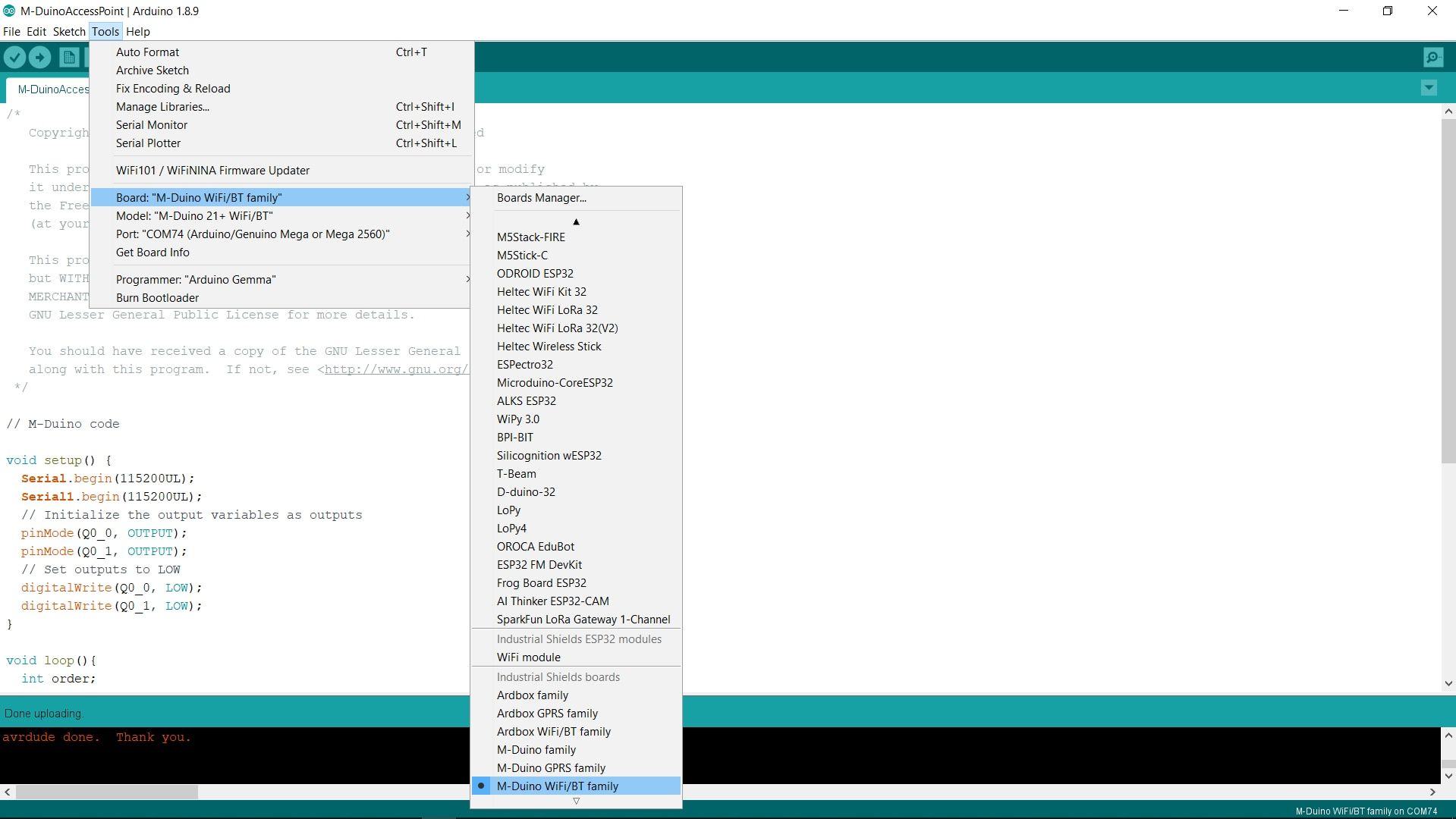
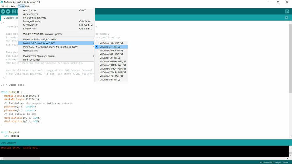
En primer lugar, seleccionamos correctamente los dispositivos y cargamos ambos códigos.
Instrucciones para el M-Duino:
.jpg?access_token=f20ad2d6-9169-45c0-afce-a73afc991500)
Instrucciones para el ESP32:
.jpg?access_token=7f0e83ad-d015-45da-ab45-42f26710409d)
Debe tener en cuenta que puede personalizar la SSID y la contraseña:
// Replace with your network credentials
const char* ssid     = "ESP32-Access-Point";
const char* password = "123456789";
Después de subir ambos códigos, debe abrir su configuración WiFi y conectar su dispositivo (el que desee utilizar para controlar el M-Duino, un PC en nuestro ejemplo) al ESP32-Access-Point. La contraseña es 123456789 aunque puede puede canviarla así como el nombre de la red como anteriormente hemos comentado.
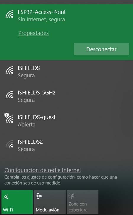
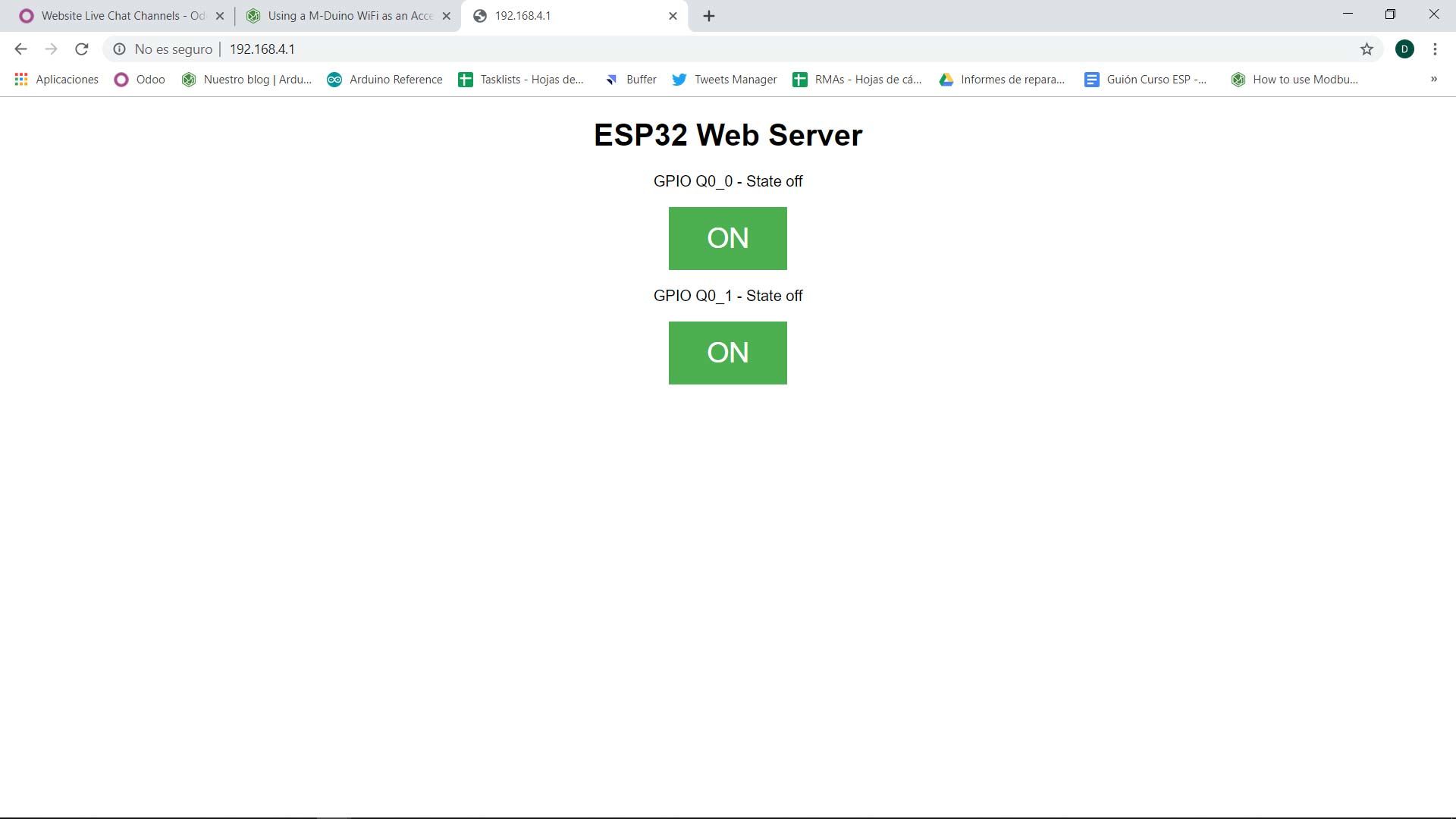
En este punto, debe abrir el navegador y poner la siguiente IP: 192.168.4.1 para ver el Servidor Web del ESP32. Y ahora, puede controlar las salidas Q0_0 y Q0_1 de su M-Duino remotamente mediante este servidor, con su dispositivo favorito y des de distintos puntos simultáneamente.
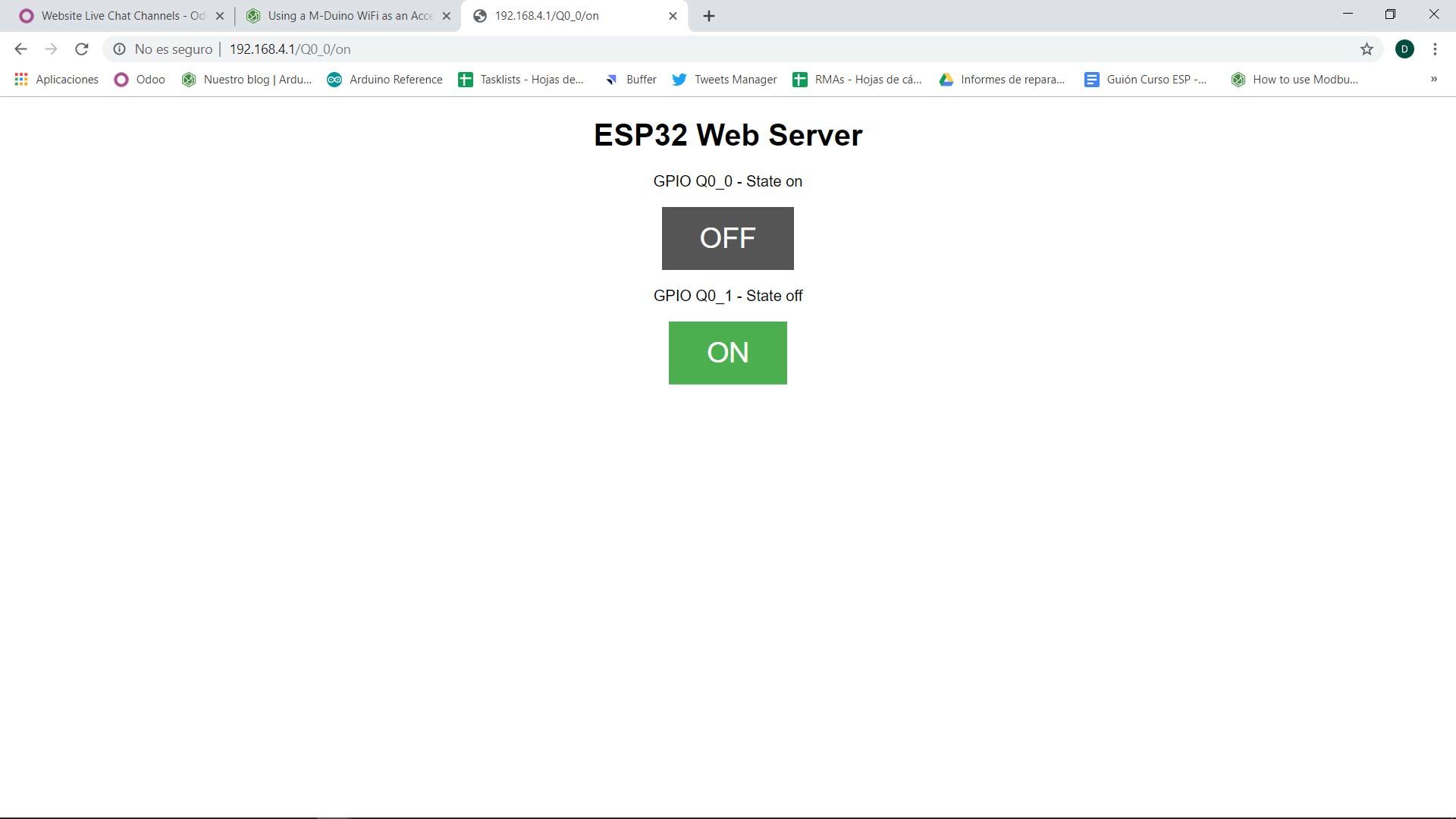
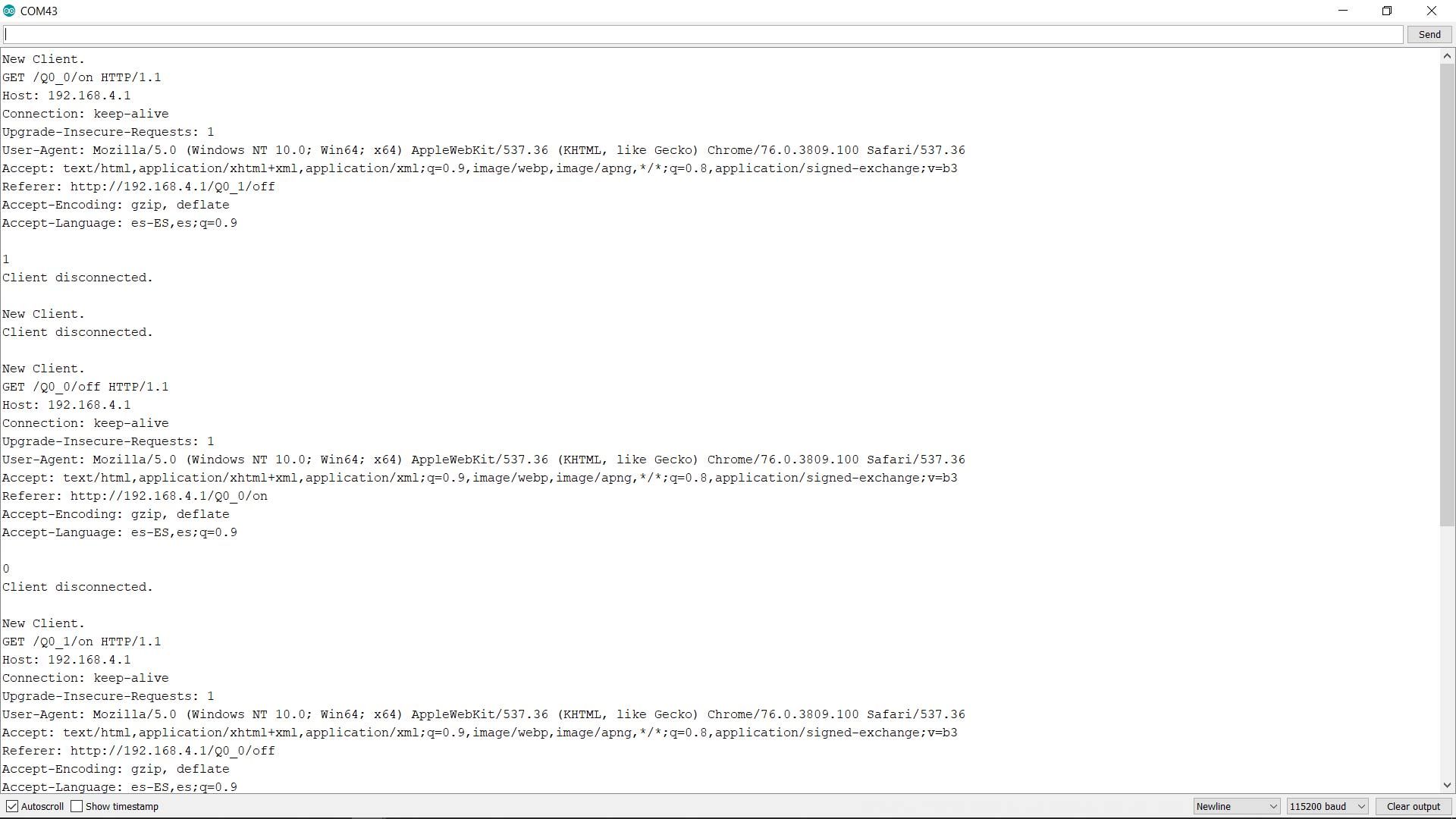
Si abre el Serial Monitor del puerto del ESP32 (asegúrese de configurar el mismo BaudRate que el código) puede visualizar toda la información de los clientes y las conexiones/desconexiones de las salidas (el número de estado).
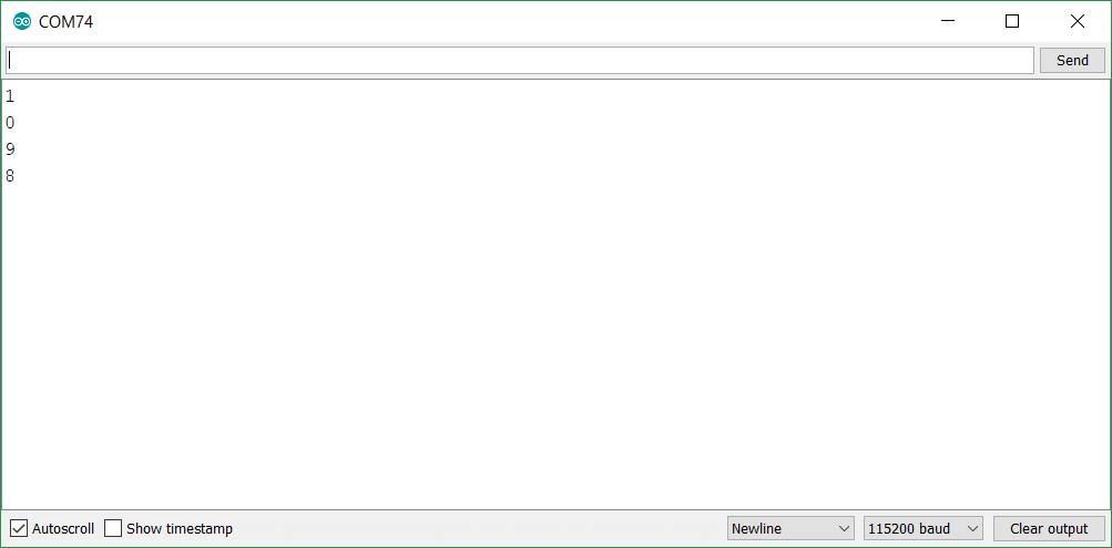
Si abre el Serial Monitor del puerto del M-Duino (asegúrese de configurar el mismo BaudRate que el código) puede visualizar las conexiones/desconexiones de las salidas (el número de estado).
