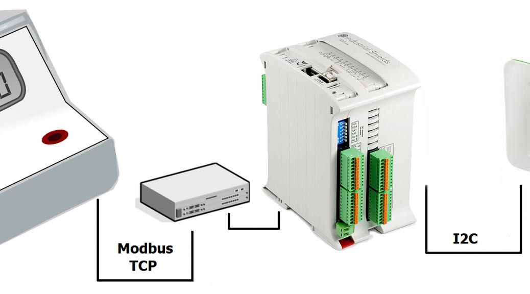
An M-Duino PLC: This controller is the heart of the system. It controls the display, generates interrupts, and controls the communication.
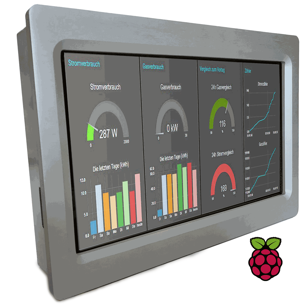
A Panel PC: Used to read on the status of a counter and display the graph of monthly consumption over the Panel Pc. – Switch will work as the interface between slaves and Master in our control network.

A Power Meter witch Modbus TCP/IP communication capabilities (as TCP is Transmission Control Protocol and IP is Internet Protocol.)
Wires and some programming experience J.
Hardware II: Communication The nice feature of Panel PC we used is that it has many interfaces such as Ethernet, USB and I²C as well. We´ve expressly chosen Ethernet because our PLC and our I2C panel have this Ethernet connecitivity. See the following picture to understand it:

Software and code Arduino sketch essentially uses the Modbus TCP library for Arduino (see the Arduino installer tutorial here). Some important things to take care when we use this library:
Insert the modbus_update function in the loop, because. takes care of the received modbus commands and will modify the registers accordingly in case of writing or reading requests.
Declare an integer array (named holdingRegs) that stores the modbus registers.
We recommend to review modbus tcp basics at http://www.simplymodbus.ca/
After that, just start sending values to the panel PC through USB I2C communication.
You can find the code to be uploaded to the PLC here: 2014111_arduino_code
You need to download libraries:
Key Benefits
The main benefits of the purposed solution are:
Time Saving: Forget to go to view and write values in notebooks, your control system will do this job for you.
Real time measurement: System provides reliable data quickly.
Digital data analysis: If you can measure it, you can improve it!