
INTRODUCTION
The Read Input Registers Modbus RTU function (Modbus Function Code: 4), is used for reading from 1 to 125 contiguous input registers in a remote device.
In this blog post, we will be reading input registers between Arduino based PLC set as client - server >
Latest Posts
MODBUS RTU
To know more about Modbus RTU and how the library works, please visit the following blog post:
HARDWARE REQUIREMENTS
B type cable , to program the Arduino based PLC
Two twisted pair cables, for RS485.
SOFTWARE REQUIREMENTS
CONNECTIONS
Now, in order to set a Modbus RTU communication, we are going to do the following:
1. Power the PLC between 12 and 24V.
2. Wire the cables through RS-485. This is based on a twisted pair cables, on cable from A+ to A+, and the other one from B- to B-.
3. Set the red switch to the Half-Duplex: HD
.jpg?access_token=98298898-085a-4ca9-8dc0-52c3e05f6054)
MODBUS RTU MASTER READ COILS
In order to set an M-Duino as a master and the other one as a slave, we will have to program both to execute each code. So, in order to program the master, we are going to do the following:
1. Go to the top bar, and click on: File > Examples > Tools40 > Modbus > and select the ModbusRTUMasterReadCoils sketch. And change the 63th line to:
    if (!master.readCoils(31, 0, 1)) {
      // Failure treatment
    }
2. Click on Tools > Board > Industrial Shields boards > And select the M-Duino family.
3. Then, select the PLC model by going to Tools > Model > And selecting the model. In our case: M-Duino 21+
4. Select the port by going to Tools > Port > And select the port of the Arduino board.
5. Finally, either click on the arrow to upload the sketch, or go to Sketch > Upload.
MODBUS RTU SLAVE
Once the master is already programmed, we are going to do the same as with the Master PLC, but choosing the ModbusRTUSlave sketch. So:
1. Change the B type cable and connect it to the other M-Duino PLC.
2. Go to the top bar, and click on: File > Examples > Tools40 > Modbus > and select the ModbusRTUSlave sketch.
3. Once the sketch is opened, click on Tools > Board > Industrial Shields boards > And select the M-Duino family.
4. Then, select the PLC model by going to Tools > Model > And selecting the model. In our case: M-Duino 21+
5. Select the port by going to Tools > Port > And select the port of the Arduino board.
6. Finally, either click on the arrow to upload the sketch, or go to Sketch > Upload.
Now, open the Serial Monitor from the Master, and read a coil of the Q0.0 input!
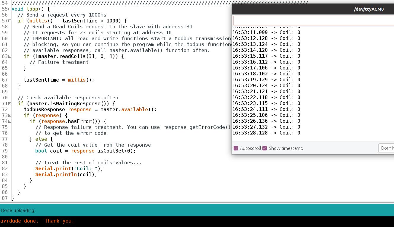
Tip: Add some value to the Q0.0 output in order to get a value different from 0