INTRODUCTION
A waveform viewer is a software tool for viewing the signal levels of either a digital or analog circuit design.
Piscope is a digital waveform viewer, or logic analyser, for the Raspberry Pi, therefore, for the Raspberry PLC too.
In this blog post, we will be installing piscope and we will check the pin activity from our programmable logic controller.
Latest Posts
PIGPIO
pigpio is a library written in the C programming language for the Raspberry, which allows control of the General Purpose Input Outputs (GPIO), and it works on all versions of the Pi.
The pigpio daemon offers a socket and pipe interface to the underlying C library. A C library and a Python module allow control of the GPIO via the pigpio daemon.
To see more features, please visit pigpio's website >
HOW TO INSTALL PIGPIO
In order to install pigpio from your Raspberry PLC, do the following:
1. Check that you have Internet connection
2. Update the package manager:
sudo apt update
3. Install pigpio
sudo apt install pigpio
PISCOPE
GTK is a free and open-source cross-platform widget toolkit for creating graphical user interfaces (GUIs).
piscope is a logic analyser or digital waveform viewer, and a GTK+3 application that uses pigpio to provide raw GPIO level data.
piscope may be run on a Pi or on any machine capable of compiling a GTK+3 application.
HOW TO INSTALL PISCOPE
In order to install piscope, please do the following:
wget abyz.me.uk/rpi/pigpio/piscope.tar
tar xvf piscope.tar
cd PISCOPE/
make hf
make install
HOW TO RUN PISCOPE
1. Run the pigpio-daemon and execute piscope.
sudo pigpiod
sudo piscope &
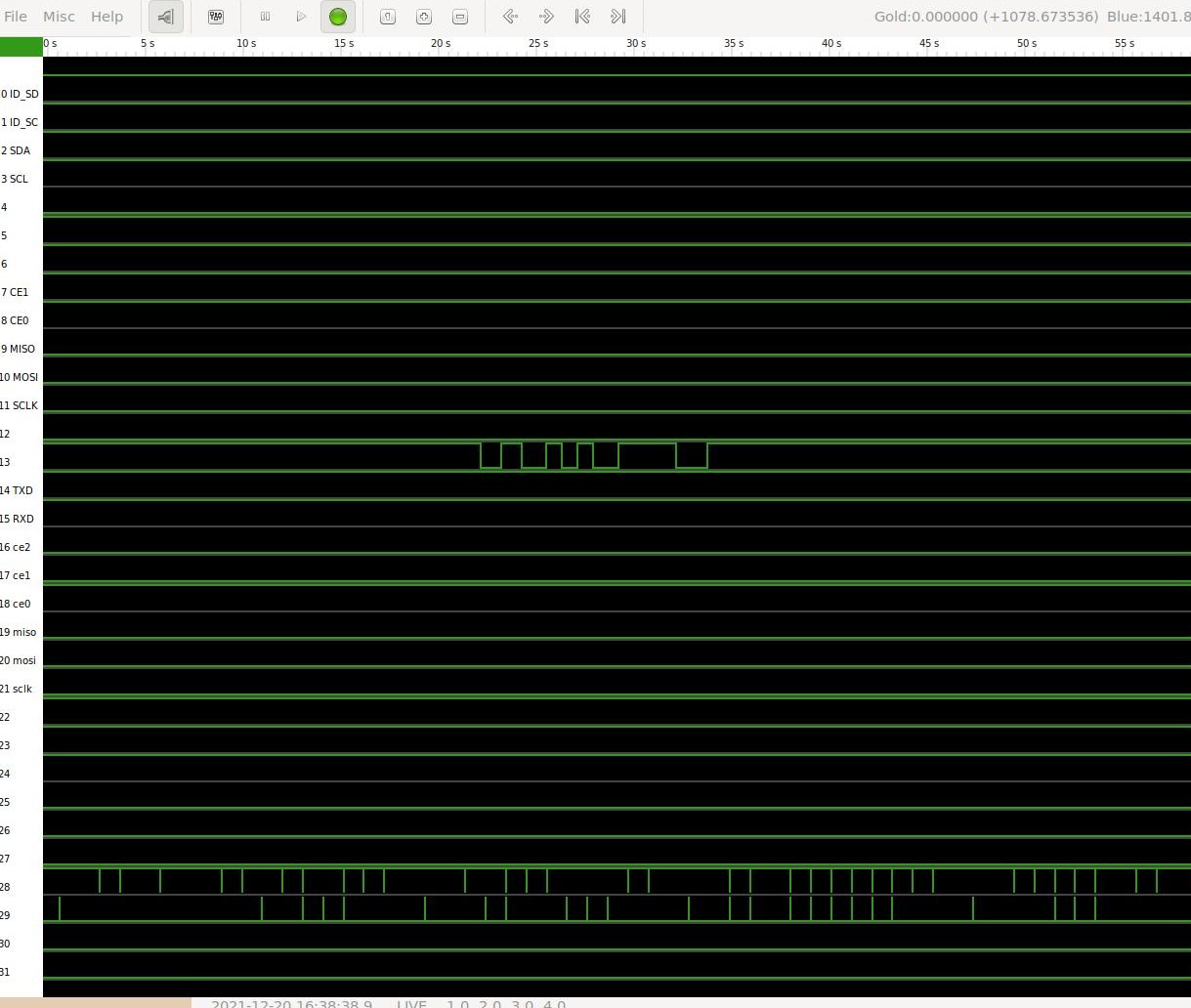
This is the window that will open, showing all the GPIO.

RASPBERRY GPIO
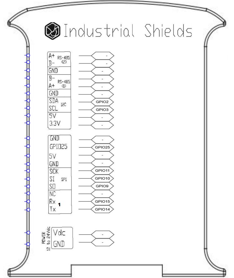
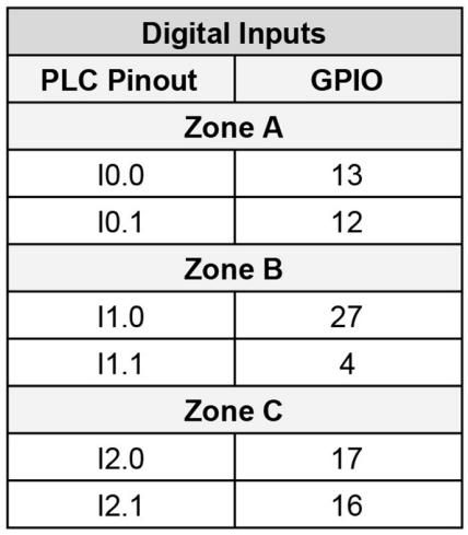
Although all the inputs and outputs from the Raspberry PLC go to an I2C chip, there are some that are not and go directly to the Raspberry Pi GPIO. These are the ones that we will be able to control, like:


You can see more information about it in the Raspberry PLC datasheet and user guides, that you can download from the Raspberry PLC product page >
TESTING
Now, choose the GPIO you want to test. In our case, we will force the value for the I0.0 input: gpio 13.
Change the input values by running:
echo 13 > /sys/class/gpio/export
echo out  /sys/class/gpio/gpio13/direction
echo 1 > /sys/class/gpio/gpio13/value
echo 0 > /sys/class/gpio/gpio13/value
echo 1 > /sys/class/gpio/gpio13/value
echo 0 > /sys/class/gpio/gpio13/value
Go to the piscope window, and monitor the GPIO from your Raspberry PLC!
